1900 SERIES FCC ID: IJ3PI1900
Prices effective August 1, 2025
1900 Series Description
When compared to previous generation equipment, the 1900 series Antenna Monitors provide better performance over a wider dynamic range with virtually no modulation effects. Separate measuring circuits are employed for each tower. Remote control interfacing is greatly simplified because these monitors provide simultaneous outputs for the measured Phase Angle and sample Current Ratio of each tower. Therefore, it is not necessary for the remote control system to select a specific tower prior to interrogating a particular telemetry output port.
To facilitate maintenance and system reconfiguration, all active circuits are packaged on plug-in printed card modules which are accessible at the rear panel of the monitor. 1900 series Antenna Monitor metering capacity (number of towers) may be increased or decreased by adding or removing individual metering modules.
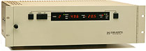
| 1901 Antenna Monitor Antenna Monitor (Two Towers, 1 to 3 Patterns) full brochure |
$ 12,900.00 |
| Monitor unit with front panel display, local operating controls, and complete interface capability to remote control systems. |
|
| 1902 Monitor Display | $ 3,450.00 |
| Display Unit for extension manual control and reading of the 1901 or 1903 Monitors (1-3/4″ Panel Height). |
|
| 1903 Antenna Monitor (Two Towers, 1 to 3 Patterns) | $ 10,750.00 |
| Monitor unit with no display or controls, for control from a Type 1902 Monitor Display, with complete remote control interface. |
|
| 1910 Tower Inputs Metering Board (1 each required for each tower) | $ 1,950.00 |
| Circuit Card for one Tower input. Provides full metering support and outputs for Phase Ratio and Amplitude for one Tower. |
BASIC CONFIGURATIONS
|
ORDERING INSTRUCTIONS
A 1901 or 1903 Antenna Monitor consists of a chassis with power supplies and a control board which can support up to (12) Type 1910 Tower Input Metering Boards. The basic unit is supplied with two (2) 1910 Boards. A four tower array would require two additional 1910 Boards for a total of four 1910 Tower Inputs. Potomac Instruments will configure a 1900 series monitor and conduct it’s final tests at the station frequency if the following information is specified at the time of the order:
| Number of Towers (2-12) | ________ Twrs. |
| Number of Patterns (1-3) | ________ Pats. |
| Nondirectional Patterns | ________ Y / N |
| Reference Tower for each Pattern | ________ D/N/3rd |
| Operating Frequency | ________ Khz |
| Sampling Line Impedance (50 or 75 ohms) | ________ Ohms |
| Input Connector Type (UHF or N) | ________ |
| AC Voltage (117, 230 or 245 VAC) | ________ VAC |
| AC Frequency (50 or 60 Hz) | _________ Hz |
SPECIAL APPLICATIONS
To the extent feasible 1900 series antenna monitors can be manufactured for low signal levels or may incorporate custom filters for applications involving interference derived from a nearby transmitter facility or from diplexing more than one frequency onto a single antenna system.
Filters are custom designed, manufactured and certified for each specific application and are thus considered to be “Custom Engineering Projects.” Potomac Instruments will design, manufacture, and test the filter performance in the specific Antenna Monitor. Potomac will also certify that the Antenna Monitor meets or exceeds its original FCC Type Approval specifications and maintain full records of each system for service and technical support.
In all cases Potomac Instruments will need to carefully define the design parameters of such filters. Accordingly, sampling system design and the specifics of the Desired to Undesired (D/U) signals that appear at the, properly terminated, RF input connectors of the antenna monitor must be understood.
If the diplexed or interfering signals are already present on the antenna the data necessary for Potomac to proceed with a design can be obtained by using a Potomac Instruments’ FIM-41 or FIM-21 to measure the relative amplitude of the desired signal and each of the undesired signals from the sampling system. Potomac will supply detailed instructions to assist in this process or the station can utilize a consulting engineer to prepare the necessary data