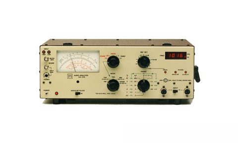
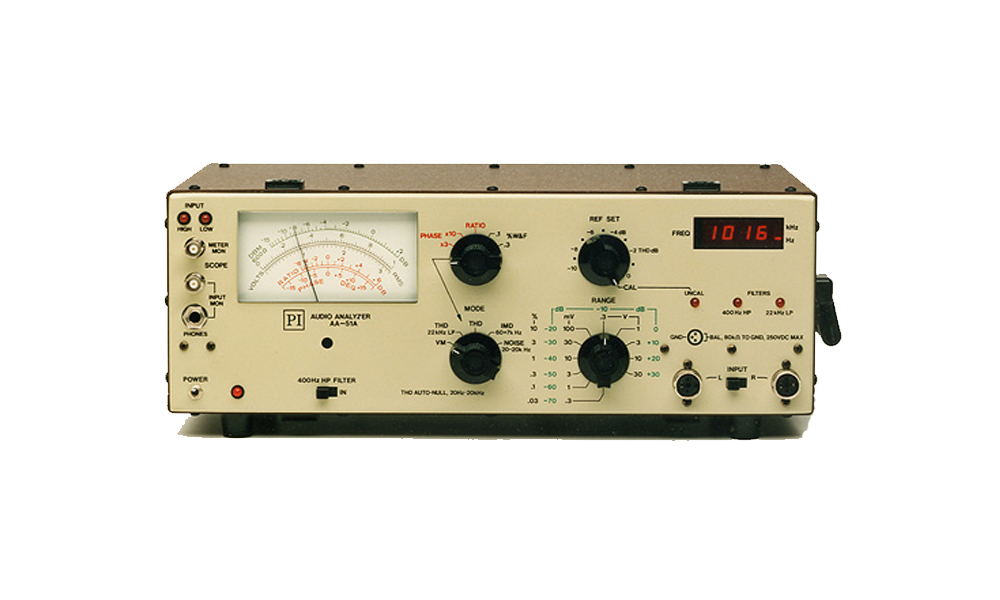
The AA-51A is a multi-purpose, precision audio analyzer that helps to automate proof-of-performance measurements and equipment maintenance. Unique features of the AA-51A make it the ideal instrument for engineers, and service professionals. Excellent RFI shielding enables measurements to be made within the high-level RF environments of commercial broadcast transmitter facilities.
Total harmonic distortion measurements are made by simply setting the Mode Switch to THD and reading the meter. The AA-51A automatically accomplishes nulling and tuning to the inputfrequency. This enables the operator to accurately measure the harmonic distortion at various discrete frequencies and different power levels much faster than using conventional distortion analyzers.
Intermodulation distortion measurements are performed with equal simplicity. Utilizing the SMPTE Standard intermodulation signal the AA-51A displays percent of IM. Measurements are completely automatic over a wide dynamic range.
Accurate frequency response measurements are facilitated by a wideband voltmeter which exhibits a flat response (+ or – 0.1dB) from 20 Hz to 100 kHz. Input level range is 1 mV to 100 V full scale. The average responding meter is calibrated to the rms value of a sinewave. For Signal + Noise/Noise measurements the voltmeter bandwidth may be restricted to 20 kHz by placing the mode switch in the NOISE position.
Incidental frequency modulation — “Wow and Flutter” — usually associated with tape decks, cart machines and turntables is measured automatically. The AA-51A measure weighted peak flutter as specified by IEEE Standard 193.
Stereo signals and mono signals derived from a stereo source are often degraded by phase errors and differential gain variation between left and right channels of a given audio system. The AA-51A contains both phase and ratio measuring circuitry which enables the operator to evaluate these characteristics quickly and accurately throughout the complete audio spectrum, and over a wide dynamic range. Phase angle is displayed with a zero center scale indication and a full scale, switch selected sensitivity of either + or – 180 degrees. The ratio meter is also a zero center scale device with a + or – 6dB full scale deflection.
The Phase and Ratio measurement features of the AA-51A are particularly useful for line equalization measurements, azimuth alignment of stereo tape heads, and trouble shooting of audio consoles, amplifiers, and networks.
- Shielded, Balanced Inputs
- Auto-Null THD
- Frequency Readout
- Compatibility with NAB Test CD’s
- Stereo Measurements
- Measures:
- THD, IMD, Volts
- Signal + Noise/Noise
- Stereo Phase
- Stereo Ratio
- Wow and Flutter
- Frequency
| AA-51A SPECIFICATIONS | |
| Input: Impedance Maximum AC Maximum DC Common-mode rejection Cable connector MON SCOPE output MON PHONES output HIGH LED on when: LOW LED on when: |
Balanced 80 k ohms+100 pF, each pin to ground 220 Vrms, each pin to ground 250 Vdc, each pin to ground greater than 60dB Switchcraft p/n 05CL3M 5.6 Vp-p for inputs from 40 mVrms to 90 Vrms, typical Set to 70mVRMS, internal adj. Input less than 80 Vrms (except for VM and NOISE) Input less than 100 mVrms, (except for VM and NOISE) |
| THD Meter: Input frequency range Measurement passband Notch attenuation RangesAccuracy Input level ranges Internal THD + noise Filters METER MON output |
20 Hz to 20 kHz, fundamental 1.7 to 12.5X input frequency at -3dB greater than 100 dB 6 ranges, 0.03% to 10% full scale, -20 dB to -70 dB full scale ± 15% (± 1.5 dB) 100 mV to 80 V 0.01% max, 0.006% typical, 20 Hz-5 kHz 0.02% max, 0.012% typical at 20 kHz 22 kHz low-pass at input, switch selected 400 Hz high-pass, switch selected 100 mVp-p, meter at full scale 2 seconds approximately |
| IMD Meter: Input signal required Full scale ranges Accuracy Input level range Internal IMD + noise METER MON output |
60 Hz + 7 kHz, 4:1 voltage ratio 6 ranges, 0.03% to 10% full scale ± 10% 100 mV to 80 V less than 0.015% 100 mVp-p, meter at full scale |
| AC Voltmeter: Frequency response RangesAccuracy METER MON output Internal noise Filter REF SET range |
10 Hz to 100 kHz, + or – 0.1dB max.variation 11 ranges, 0.3 mV to 30 V full scale, -68 dBm to +32 dBm full scale ± 3% 100 mVp-p, meter at full scale 20 uV(-92 dBm) maximum 400 Hz (at -3 dB) high-pass, switch selected greater than 10 dB |
| Noise Meter: Frequency response Ranges Accuracy METER MON output Internal noise Filter REF SET range |
20 Hz to 20 kHz at -3 dB 11 ranges, 0.3 mV to 30 V full scale ± 3% 100 mVp-p, meter at full scale 15 uV (-94 dBm) max. 400 Hz (at -3 dB) high-pass, switch selected greater than 10 dB |
| Phase Meter: Measurement ranges Accuracy Polarity Input frequency range Input level range METER MON output |
± 54 degrees and + or – 180 degrees full scale ± 3 degrees Positive angle means L leads R 20 Hz to 20 kHz 100 mV to 80 V Rectangular wave at input frequency, duty cycle proportional to angle |
| Ratio Meter: Measurement ranges Accuracy Polarity Input frequency range Input level range METER MON output |
± 6 dB ± 0.2 dB Positive ratio means R greater than L 20 Hz to 20 kHZ 100 mV to 80 V dc voltage proportional to ratio |
| Wow & Flutter Meter: Measurement ranges Input frequency Accuracy Input level range Internal Noise METER MON output |
0.1% and 0.3% full scale 3.15 kHz ± 10% ± 10% 100 mV to 80 V less than 0.01% 500 mVp-p at full scale, passband 0.2Hz-200Hz |
| Frequency Counter: Frequency range Resolution Accuracy |
10 Hz to 200 kHz less than 900 Hz (approx.), 0.1 Hz 900 Hz to 9000 Hz (approx.), 1.0 Hz 9 kHz to 24 kHz (approx.), 0.01 kHz greater than 24 kHz (approx.), 0.1 kHz -1 to 0 count error in RH digit (LSD) 1 mV to 80V |
| Power: 117 Vac (230 Vac option) |
50/60 Hz, 10 W |
| Weight, lb (kg): | 5.44 (12) |
| Dimensions, in. (cm):
Optional Rack Mount |
15.25 (38.74) W; 5.25 (13.34) H; 10.125 (25.72) D 5.25 (13.34) Rack space rqd. |
Specifications subject to change without notice.