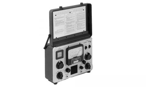
The Models FIM-22 and FIM-41 are portable field strength meters designed to provide precise, direct measurements of electro-magnetic fields in the 200 kHz to 5.0 MHz spectrum. These units include a receiver, integral shielded loop antenna, precision attenuator, internal calibration source, and battery power supply. With calibration accuracy traceable to the National Institute of Standards and Technology, the FIM-22 and FIM-41 meet the most exacting requirements of government and industry. Their hinged covers, on the rugged drawn aluminum cases, contain a loop antenna. Opening the cover to a vertical position connects the antenna terminals to the receiver via maintenance-free gold-plated contacts. An interlock switch prevents inadvertent battery discharge when the cover is closed.
SYSTEM OPERATION
A simplified calibration procedure assures measurement accuracy. Frequency is easily selected and observed on an illuminated dial. Tuning the receiver simultaneously tunes the calibrating oscillator to within a few kHz of the selected frequency. A separate control is used for vernier tuning. Proper gain calibration is precisely indicated by a sharp null on the meter when the gain control is adjusted for an exact balance between the detected outputs of the receiver and the calibrating oscillator. Field strength is displayed on the meter’s logarithmic scale which is calibrated in increments from 1 to 10. Full scale meter sensitivity is determined by the attenuator range switch. Signal ratio (i.e., harmonic) measurements are easily resolved using the dB scale of the meter in conjunction with the 20 dB per step range switch.
- 6-Position Attenuator, 20 dB/step
- High Q Double-Tuned RF Input for Maximum Image Rejection
- Multi-Pole Hybrid IF Filter (Shape Factor, 2.2:1)
- Temperature Compensated and Voltage Regulated
- 4-Inch, Lighted, Mirrored Scale, Taut-Band Meter
- Front Panel Speaker, Headphone Jack, and Recorder Output Jack
- RF Coaxial Input
- Mechanical “Vernier” Tuning
- Differential Circuit for Precise Calibration
- Capable of Signal Ratio Measurements to -80 dB
| FIM – 22/41 SPECIFICATIONS | |
| Frequency Range: FIM-22 FIM-41 |
200 kHz to 550 kHz 540 kHz to 5.0 MHz in two bands: Band “A” 0.54 MHz to 1.61 MHz Band “B” 1.58 MHz to 5.0 MHz |
| Field Intensity Range: | 10 uV per meter to 10 V per meter |
| Accuracy of Calibration: | 1%, referenced to NIST Standard field (Calibrated at 220 mV per meter) |
| Accuracy of Range Attenuator: |
2% over entire FI range and tuning band |
| Selectivity: FIM-22 Bandwidth (6 dB) Bandwidth (60 dB) IF Rejection Image Rejection |
4 kHz nominal with multi-pole hybrid filter 10 kHz maximum 70 dB minimum; 40 dB minimum at 455 kHz 60 dB minimum |
| Selectivity: FIM-41 Bandwidth (6 dB) Bandwidth (60 dB) IF Rejection Image Rejection |
7 kHz nominal with multi-pole hybrid filter 15 kHz maximum 35 dB minimum 65 dB at 540 kHz decreasing to 45 dB (minimum) at 5.0 MHz |
| IF Frequency: | 455 kHz |
| Panel Meter: | 4″ mirrored scale, logarithmic graduations 1 to 10, taut band meter movement, 3% linearity |
| Antenna: | Shielded loop, integral part of hinged cover |
| Audio Outputs: | Front Panel loudspeaker, weather treated cone Headphone jack, high and low Z (disconnects speaker) |
| Recorder Output: | 0.4 to 4 Vdc proportional to field intensity for each attenuator range, source resistance 2200 ohms |
| Lights: | Frequency dial and meter; panel switch for night use |
| Batteries: 6 required | Standard 1.5 V C-Zn “D” cells or 1.5 V Alkaline cells for extended life at very low temperatures |
| Battery Life: | Greater than 1000 FI readings (reduced life with frequent use of lights and/or high speaker volume) |
| Ambient Temperature, F (C): | Continuous exposure -10 deg. (23 deg.) to 130 deg. (54 deg.); “reading time” exposures practical at lower temperatures. |
| Dimensions. IN. (CM): | Cover closed: 8.75 (22.2) H, 11.5 (29.2) W, 5.125 (13) D Cover open: 3.875 (9.8) D – (gripping width) |
| Weight, LB (KG): | 12.0 (5.5) with batteries |
| External RF Input: FIM-22 FIM-41 |
200 kHz to 550 kHz, 10 uV to 10 V 540 kHz to 5.0 MHz, 10 uV to 10 V |
| RF Input Switch: | Selects loops antenna (ANT) or panel connector (EXT) |
| Meter Switch: | Selects normal linear (LIN) or logarithmic (LOG) operation |
| Logarithmic Dynamic Range: | 60 db compressed input range for FI meter and recorder input |
Specifications subject to change without notice.
