


SD-31 Frequency Synthesizer-Detector
A Synthesizer-Detector providing a high output crystal signal generator of precisely known frequency combined with a sensitive, selective detector for RF bridge measurements of AM antenna impedance.
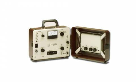
The Model SD-31 Synthesizer-Detector is a high output crystal signal generator of precisely known frequency combined with a sensitive, selective detctor for RF bridge measurements of AM antenna impedance. Packaged in a single light-weight battery-powered unit, the SD031 complements bridges such as the General Radio 1606, 916, and the Delta OIB-1.
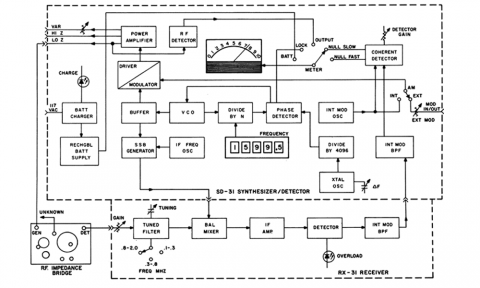
A frequency synthesizer determines the generator frequency, which can be adjusted in 0.5 KHz steps by means of a front-panel switch from 100.0 KHz to 1999.5 KHz. Frequency accuracy is the same as that of the internal reference oscillator. A front panel fine-frequency control varies the frequency up to ± .01 percent. The generator can drive a wide range ofload impedance at levels up to 20 volts RMS. It also has a variable low-level output suitable for driving a counter or for receiver frequency calibration.
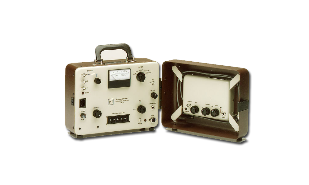
The SD-31 uses for detection a coherent detector which rejects interfering signals picked up by the antenna. In this arrangement, the generator is mudulated at a low frequency, and the SD-31 detector circuit responds only to a signal having that particular modulation. A sensitive and selective receiver connected to the bridge detector output is required; this can be the Model RX-31 Receiver, available as an option with the SD-31, or an external receiver such as the Potomac Model FIM-21 Field Strength Meter. The optional RX-31 Receiver is designed to work witht eh SD-31 and is automatically tuned to the generator frequency. The SD-31 is powered by a rechargeable battery adequate for 4-8 hours of use between charges. Battery recharging is possible while the unit is operating.
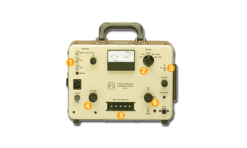
- OUTPUTS: VAR Output and Control – varies output level at VAR connector for low level applications
LO Z – hight level output for connection to bridge for Z less than 180 ohms.
HI Z – high level output for connection to bridge for Z greater than 180 ohms. - METER FUNCTION SWITCH:
BATT – indicates charge level of batter supply
LOCK – provides positive indication that output frequency is locked to crystal reference oscillator frequency
OUTPUT – indicates relative output of power amplifier
NULL SLOW – provides highly damped indication of coherent detector output.
NULL FAST – provides undamped indication of coherent detector output. - AM SWITCH: Selects internal (INT) or external (EXT) Amplitude Modulation of RF output
- DET GAIN: Adjusts gain (sensitivity) of coherent detector
- FREQ 100.0 – 1999.5 KHz: Sets synthesizer output frequency within indicated range with separate thumb sheel switches for each digit
- F CONTROL: Enables operator to vary synthesizer output frequency slightly above or slightly below the nominal value
- Designed for Antenna impedance measurements with RF bridges in the presence of strong interference
- High-level oscillator compatible with General Radio 1606 Series, 916 Series, and Delta OIB-1 Impedance Bridges
- Frequency crystal controlled, variable in 500 Hz steps from 100.0 kHz to 1999.5 kHz
- Versatile – can be used as an RF signal generator for trouble-shooting antenna systems; as a variable frequency oscillator for antenna site survey; or other applications requiring a precise frequency source
- Special Coherent Detector circuit rejects interfering signals experienced during antenna measurements
- Receiver for Detector can be external or optional built0in RX-31 Receiver
- Powered by rechargeable batteries
- Self-contained portable package
| SD-31 SPECIFICATIONS | |
| Frequency | 100.00 – 1999.5 kHz switch selected, 500 Hz steps |
| Frequency Accuracy | ±005. +200°F to +1000°F |
| Frequency Vernier (AF) Adjustment Range |
±.01% of frequency approximately |
| Output Levels | HIZ: 20 V RMS with 1000 ohmload (use for Z>180 ohms) LOZ: 8 V RMS with50 ohm load (use for Z<180 ohms) (HIZ & LOZ: minimum levels with fully charged battery) VAR: 100 mV RMS approximately with 50 ohmload |
| AM Modulation | Internal: 40 Hz (approximately) square wave External: 1.0 mV max. required to produce 50% modulation, 300 Hz – 3 kHz. |
| Detector Input Requirement (from external receiver) |
1 V RMS approximately across 100 K ohms for 100% modulation of receiver RF input at 40 Hz. |
| Metering (Switch Selected) | Battery voltage Phase loop locking Output monitor Detector null, fast or slow response |
| AC Power Unit | 105-130 VAC, 50-60 Hz, 15 VA (when charging) |
| Dimensions | Height – 9 1/2 inches Width – 11 1/2 inches Depth – 6 1/2 inches |
| Weight | 12 lbs. |
| Battery Operation Time | 8 hours approximately after full charge depending on frequency and load. |
| Battery Operation Time | 16 hours (unit not in operation) |
Specifications subject to change without notice.